Document Setup
In general, an FRC robot is too complicated and has too many parts to be created entirely within a single document. Doing so is possible, but will result in bad loading times and, likely, poor organization.
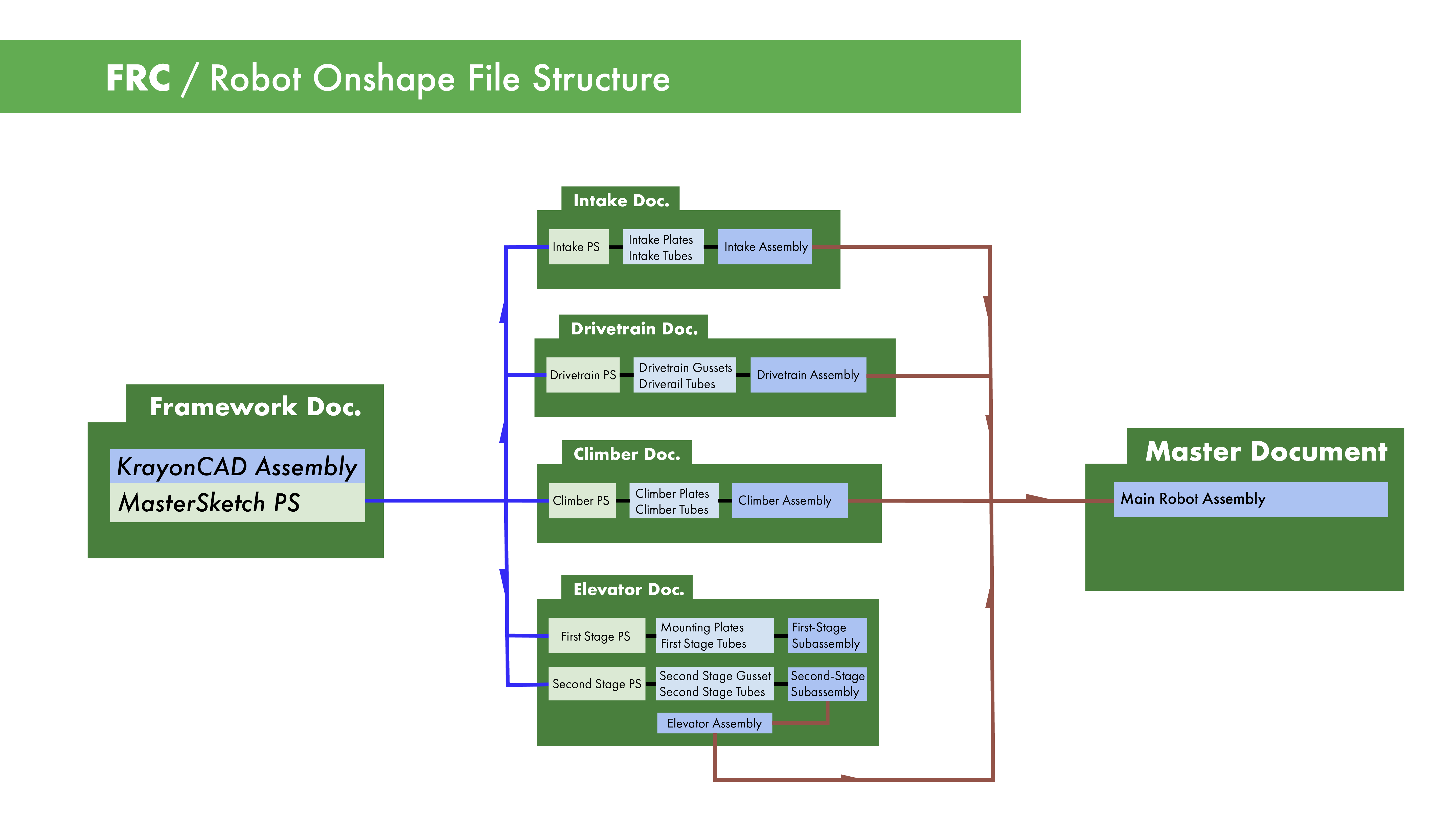
To alleviate these challenges, we generally split FRC robots into several documents, each with an individual version number:
- A "Concept" document, which contains the main layout sketch. This, alongside the Crayon CAD (a simplistic model of your robot archetype), determines the overall architecture and geometry for the robot.
- Several "Subsystem" documents, which contain the part studios, subassemblies and top-level assembly for each subsystem, such as an Intake.
- A "Main Robot" document, which contains the top-level full robot assembly. This assembly is comprised of the top-level assembly from each of the subsystem documents.
To connect these documents to each other, we make use of a few key Onshape features:
- Derive feature: brings your main layout sketch from the concept document into the subsystem document, so you can design your parts on top of it.
- Import: Subassemblies are imported from each subsystem document so they can be assembled in the main robot document.
Here is a diagram showing the full file structure:
Note
Sometimes the "main robot" document is combined with the "concept" document. In this case nothing really changes, the file structure just becomes a sort of loop, and there is one less document.
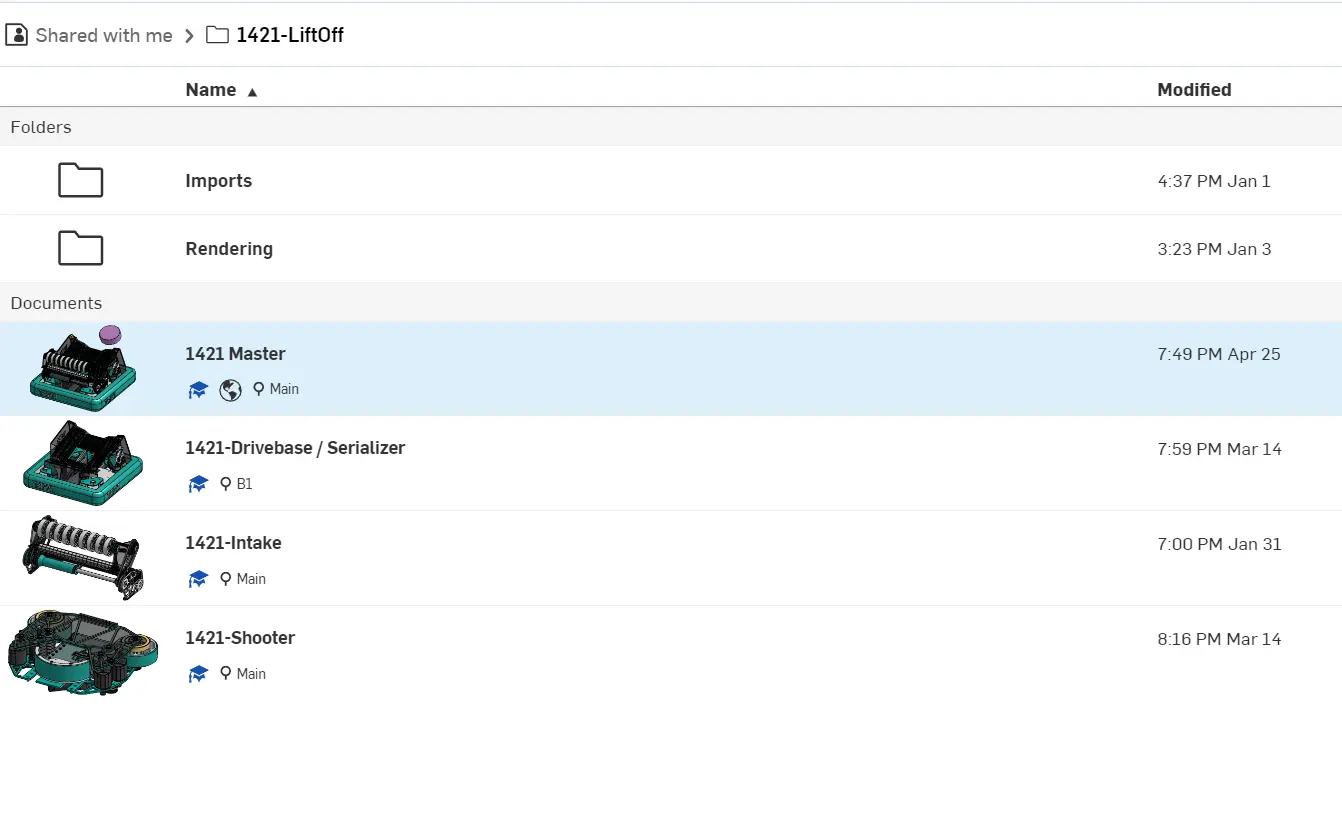
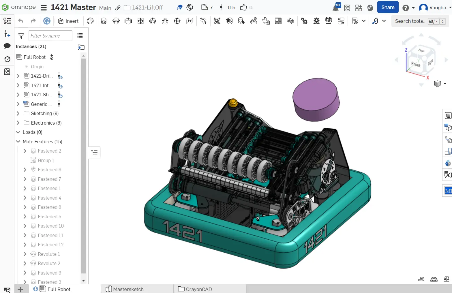
You can see an example of this document structure here. Note the combination of the framework and main documents.
The document structure isn't set in stone; as long as it helps your team fulfill the goal of top-down design and uses separate documents to split up the versions of mechanisms, you can place your main layout sketches wherever you want (main document, concept document, or the drivetrain document).