Layout Sketch Best Practices
A main layout sketch is a series of sketches that capture the major dimensions of each mechanism, field element interactions, and robot size constraints. Then, the main layout sketch(es) are inserted into each mechanism's part studio and the individual components are then modeled around the imported layout sketch. This enables much easier integration with a top-down design approach.
| Always Include | Sometimes Include | Never Include |
|---|---|---|
| Drivebase dimensions | Gears | Specific details like the shape of plates |
| End-effector wheel locations based off of prototyping | Belts | Gussets |
| Field elements and extension limits | Chain | Mounting holes |
| Mechanism motion paths | Motor locations | |
| Gamepiece path |
This isn't an extensive list, and things can vary from team to team and from architecture to architecture. Detail can easily be added or removed later if necessary.
All important measurements that drive the geometry of the robot exist in the layout sketches part studio. They can all be easily viewed and changed together, as opposed to if you had to go through each subsystem to make changes to the geometry to try to make things fit in the top-level robot assembly.
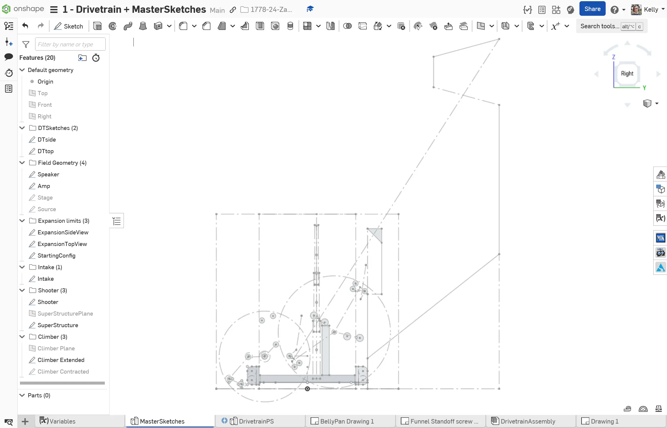
Main layout sketches always start with your drivetrain, bumpers, initial configuration, and extension limits. Field elements are sketched next. You can use hard alignment against bumpers to ensure your geometry can score pieces without much software or mechanical complexity.
Tip
Directly after kickoff, you can create a part studio with layout sketches of the drivetrain, extension limits, and field elements. This can be copied and used to test out the geometries of several different robot architectures to then decide between.
Your robot should be designed specifically to interact with the field elements and gamepieces. For the main layout sketches, this means making every dimension of every subsystem intentional, whether it's based off of field elements, extension limits, or each other.
Example
The length of an elevator would be driven by the start and end positions of the manipulator being moved, since those positions are based on how it interacts with the field elements.
Tip
You can make construction circles representing the range of motion of a pivoting subsystem, and dimension a subsystem a distance away from that circle to make sure there's clearance between them.
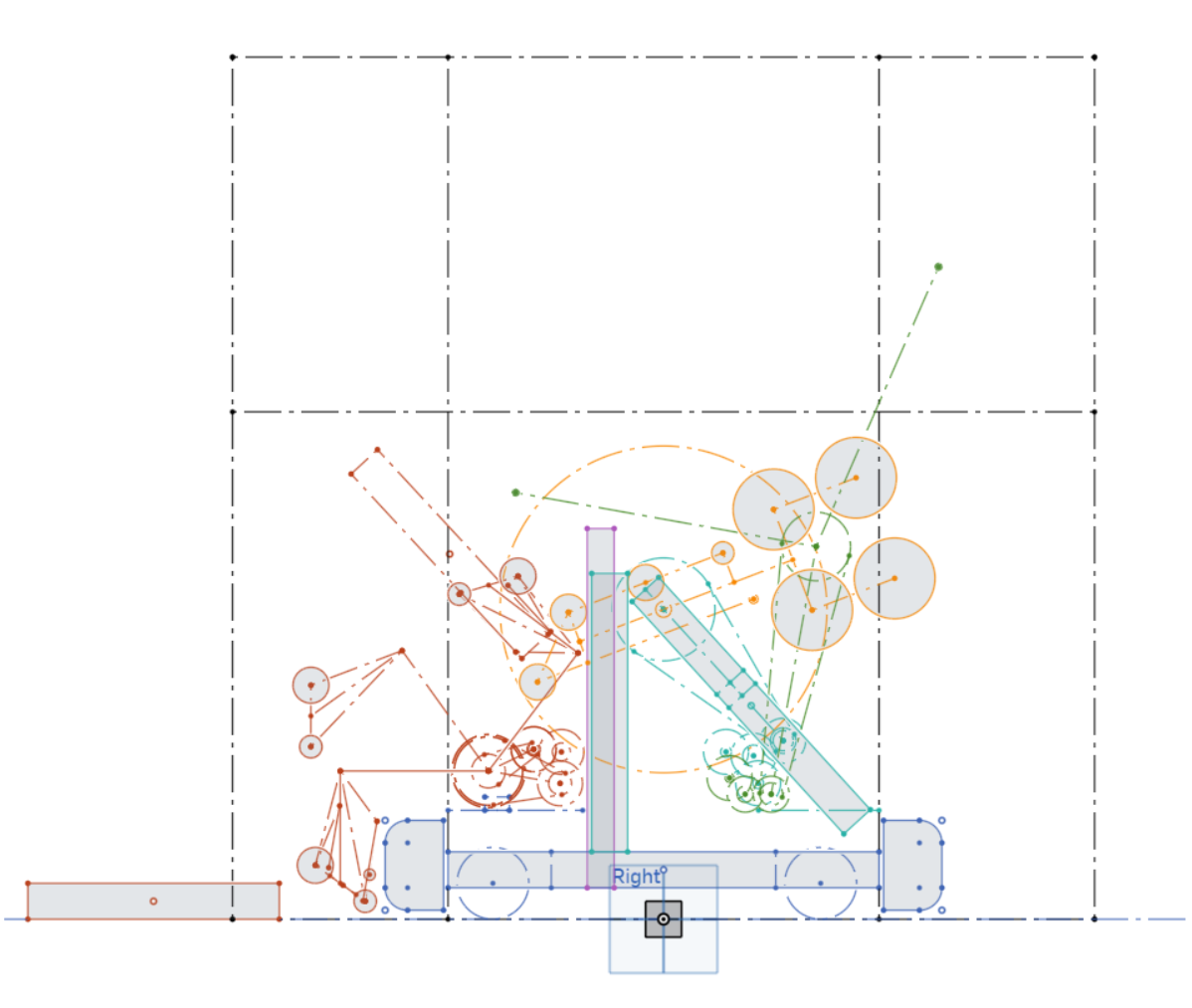
Effective layout sketching requires you to stay organized. This means:
- Multiple sketches, usually one per subsystem, within the main layout sketch part studio. Keep everything separate!
- Name your sketches accordingly
- You can also give your sketches different colors to differentiate between them
- Sketch all the possible states of each moving subsystem
Layout sketching is an art that can require some practice to get the hang of. While Stage 3 will help you learn and practice doing full layout sketches, this tutorial can help you get started if you are unsure.
A presentation of an example: 8177 Vector 2023 Robot